Disclaimer : Please note that this is an electronic kit, assembly should be done by adults only. This project is not intended for use by children, it contains small parts that could be swallowed. Your safety is your own responsibility, including proper use of equipment and safety gear, and determining whether you have adequate skill and experience. Power tools, electricity, and other resources used for these projects are dangerous, unless used properly and with adequate precautions, including safety gear. Some illustrative photos do not depict safety precautions or equipment, in order to show the project steps more clearly.
Having said that let’s start!
It’s better to start with software installation and modification, because after assembly memory card is not easily accessible (you need to re-open the casing to access).
A- Software preparation for Retropie
1 – Software installation
- Download retropie image file : https://retropie.org.uk/download/ choose the raspberr ypi 0/1 version direct download link here
- Extract the archive to get the .img file
- Plug the micro-SD in your computer
- Download, install and launch Win32diskimager
- Select the microSD drive (double check to select the micro-SD or you may format your harddrive!)
- Browse to find the .img file of retropie
- Burn the image
You can also check on youtube for video tutorials.
2 – BEFORE-assembly, software modification – IMPORTANT
Open the microSD folder on your computer and in the root you should have a config.txt file. Replace the it with:
- For RetroPie 4.8 : this one (right click “save target under…”).
- For version 4.3-4.7 I am not sure which will work as I have not tested. Please test both.
- For RetroPie 4.0-4.2 : this one.
- If you use older version on retropie you can edit your config file manually with the following instructions.
3 – AFTER-assembly, software modification
a – Increase text size
With basic theme (because you have plenty of different themes in Retropie!) the text will be a little bit small to read the game names casually. To solve it two possibilities:
– If you want you can use a theme specially designed for those 3.5″, I would suggest trying these one for example
– If you want to keep the default theme you can do the following (Source here):
- Plug a USB keyboard and press F4 to exit emulationstation and get to the console
- Type :
sudo nano /etc/emulationstation/themes/carbon/carbon.xml
- Search the file for “fontSize” parameter that is 0.03 by default and change it to 0.05.
- You should edit this parameter at 2 different places in the file (note : file is not the same as picture in source link anymore)
- press ctrl+X to exit file, then you are asked if you want to save, type “Y” and press enter
- Then you can launch the emulation station again by typing : “emulationstation” and press enter
b – Increase software volume to reduce white noise
While in emulationstation press start, select audio settings, increase to 100% then you can reduce thumbwheel potentiometer thus reducing the overall white noise
c – Installing games :
Easier is to use a USB stick, see the following tutorial :
https://github.com/retropie/retropie-setup/wiki/Transferring-Roms
Any software issue? Or want to setup recalbox? Have a look on the forum : forum.8bcraft.com
B – Hardware assembly
IMPORTANT :
- Before anything, please make sure you are not charged with static electricity when opening raspiboy kit because you can damage it. Even break it with electrostatic charge. To make sure you are not charged you can touch any grounded metal : the water tapes of your kitchen or ground pin of a power socket. Click HERE to read more.
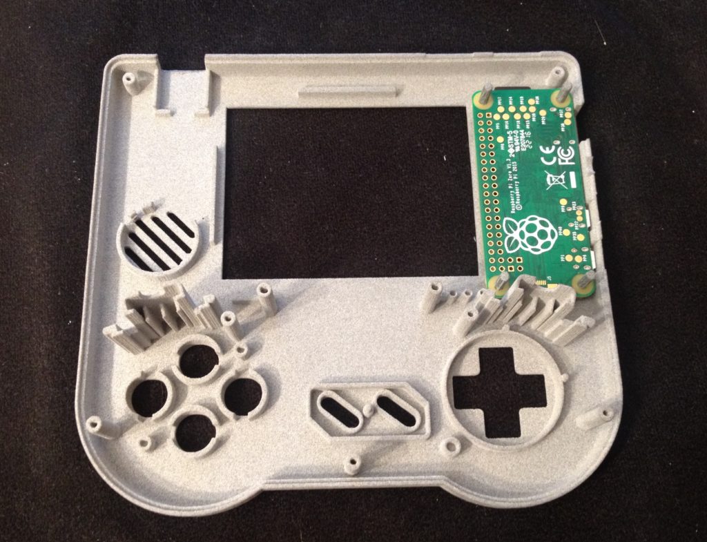
- Please be very careful when placing the raspberry pi zero. Because if you put it the wrong side you will damage/break it and the memory card. When placed in the casing you should see the back of the raspberry pi zero. You should see the face without the components. And the SD card should be on top.
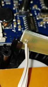
- Be carefull not to break the L/R wires (and others soldered wires) as they can break if you move them too much in all directions. Be gentle with them! See here a L button with broken wire:
- Please double check that you replaced/edited config.txt file to enable audio. If you do not then raspberry pi zero GPIO will output 3.3V instead of audio signal. Thus it will make your speaker non working and burning hot.
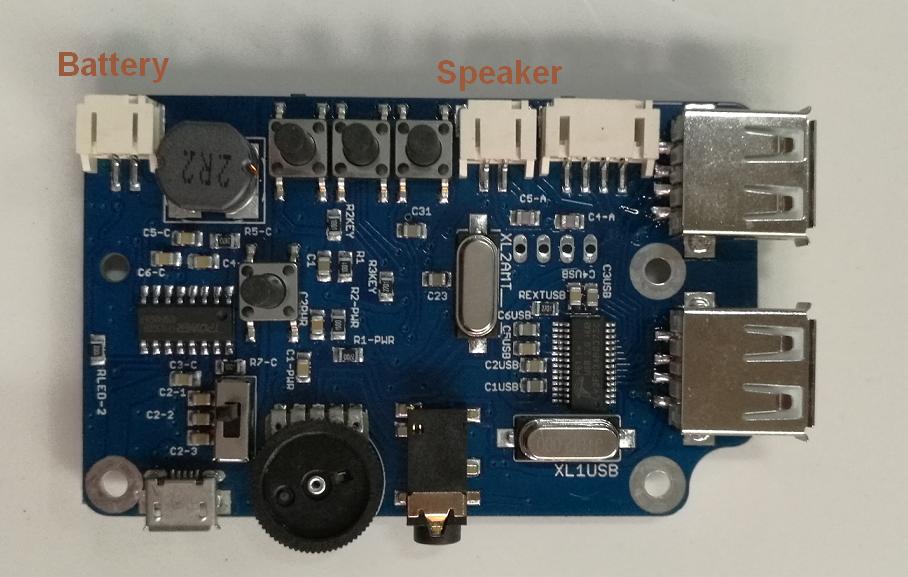
- Be carefull not to swap/reverse the speaker cable and the battery cable or the PCB will be damaged:
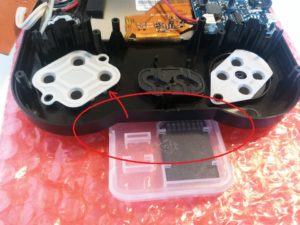
- Read this tip when you are closing the casing : If you let the front casing flat on the table, the buttons will be pushed up. So the silicon may move a little bit resulting in some buttons not working correctly. To help closing you can use a piece of something (the SD box for example) under the casing close to the buttons to prevent them to push up.
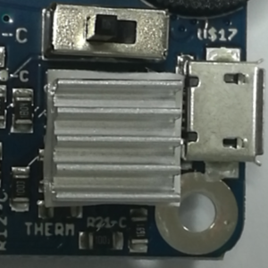
- For the v1.2 few PCB have a defect that has been through our tests. It’s a shortcut in the battery charger. So please before starting assembly do the following test : Connect the battery into the battery connector (nothing more, let the switch off and nothing else connected). Then check if the heatsink is getting very hot in few seconds. It should not. If it does get hot (while system is OFF and no charger connected) please unconnect the battery and contact me for replacing the PCB
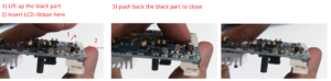
- For the v1.2 PCB the LCD ribbon connector changed, the opening black part is reversed, but it’s the same, you just have to lift it.
Two assembly videos are available, one with my ugly french accent and one by ETAPRIME, choose according to your liking:
IMPORTANT
Please be carefull with electrostatic. In 97% of the case you will be fine so sorry to bother you all with that. But the remaining 3% will contact me for various reasons : black LCD, no USB working or others. All those issues are because of electrostatic damage. So please (especially if you have carpet) be carefull. If you have a doubt please handle the PCBs only by the edges and do it with a room without carpet.
Where to get Raspberry Pi Zero? CLICK HERE
C – User manual / important notes :
1 – To turn ON the Raspiboy use the switch. To turn off the Raspiboy first shutdown from software, then when LCD goes crazy use the switch.
2 – V1.1 Raspiboy should not be used while charging. It might cause failure of the PCB. Also when plugging/unplugging power cable into a turned ON Raspiboy it might crash the unit.
3 – To switch to HDMI you need to turn OFF the Raspiboy, plug the HDMI cable, turn ON the unit. Same if you want to switch back to composite
4 – The micro-USB connector is for CHARGE ONLY. You should not try to connect a device there or try to connect SSH through that connector it will fry the PCB.
5 – Maximum current output for USB connectors all together is 0.5A. If you use devices that need lot of power like wifi-dongle, external harddrive and so on. It will disable USB power rail.
6 – V1.2 Has some difference :
- Button with a lightning bolt at the back is now a GPIO button(GPIO 17 (= pin 11)). LEDs changed, it is now :
- LED1 ON : System ON
- LED2 ON : low battery
- LED3 ON LED4 ON/OFF : battery charging
- LED3 OFF LED4 ON : charge done
- Charge and play simultaneously is working fine. Although charge may be slow while playing.
D – First boot tips :
1 – When configuring the gamepad at the beginning, when your done with all the controller’s buttons you should hold any button to skip the remaining ones.
If your controller is not recognized (can’t configure it) it can be different causes. See HERE
2 – If using old retropie version, before trying to add your games you have to go in retropie/raspi-config then option 1. Expand file system.
3 – To reduce white noise of the speaker you should increase the software volume setting (press start, audio settings). By default it’s about 60%. After increasing it you may lowering the sound with thumbwheel pot. It will reduce the white noise.
Please consider leaving a review/comment on Raspiboy!! It helps me building trust on my website. It can be left HERE
E – For Extra USB :
1. Remove thin plastic with cutter or shard blade
2. Solder the extra USB to the 8BCraft PCB at the back. Color code is :
Black : GND
Green : D+
White : D-
Red : 5V
3. Use small piece of double face tape from battery to stick the USB to the casing where you chopped the thin plastic part.
F – Adding an micro SD extension ribbon
Thanks EMaDeLoc for this nice tutorial !