READ FIRST
If you have a trouble with your unit please first check the list of problem below. Then :
- if it’s SOFTWARE problem please post on the forum : forum.8bcraft.com
- If you tried everything below and still have HARDWARE problem please open a ticket on the website and specify :
- ORDER/BACKER number and shipping name
- FULL (and clear) description of the problem and what you tried, how it happenned.
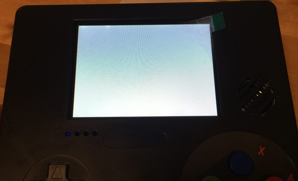
LCD shows lines like this :
This kind of line means that AMT630A (IC that drives the LCD with raspberry pi composite signal) does not receive signal.
- What raspberry pi zero do you use v1.3 or W? (reminder v1.2 is not supported). It is a new one or have you used it before, does it has solder on pads/bias? Solder can prevent good contact with pogo pins.
- Double check the Raspberry-pi Zero sits in the right side/position.
- Are you using the 8BCraft SD card? If you use one of your own maybe it’s not compatible with raspberry pi zero.
- What software have you installed on SD (recalbox need a special step to enable LCD)? How have you installed it? Did you used win32diskimager as described in assembly tutorial?
- If you use a SD that you used before on another raspberry pi, please double check config.txt configs, that there is no “force HDMI” option.
- Check if the LCD cable is attached correctly in his connector.
- Check that the pogo pins and your raspberry pi zero test pads/vias are clean, that there is not grease of whatever. You can clean them softly to be sure.
- Check (in the dark room) through the micro-USB port hole if you can see the raspeberry pi zero activity LED turning on and blinking?
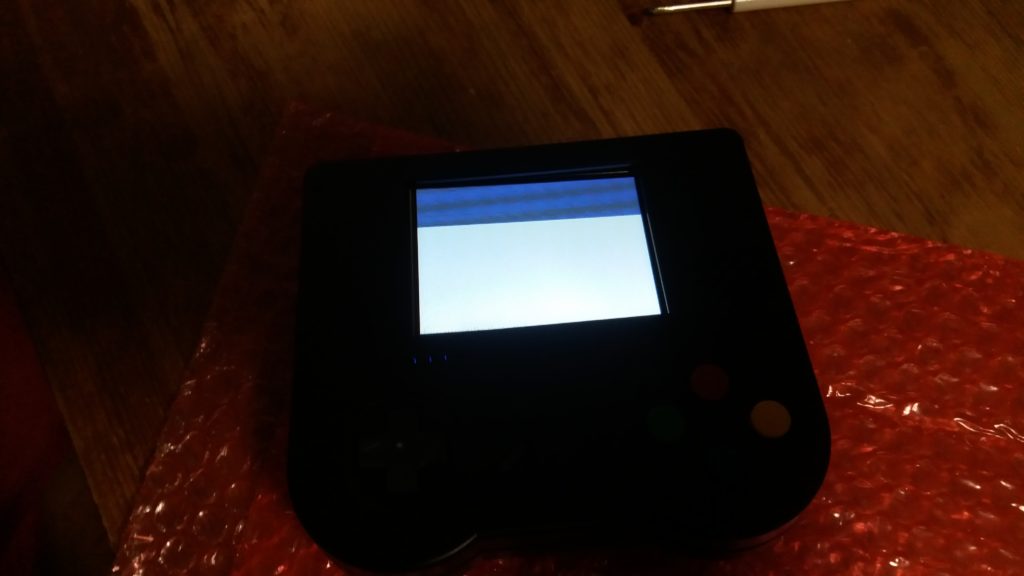
LCD is full white?
Full white screen usually happens in two cases :
- The screen ribbon has been teared. Can you check if the ribbon is teared?
- The connector is not correctly closed, so there is not enought pressure to connect the ribbon to the connector. Have you pushed the black part all the way down ?
1.2v PCB overheating when battery plugged in and system OFF :
If PCB charge chip is overhating when system is off, then the PCB is defective and needs to be replaced..
LCD shows nothing/is black but the LEDs turn ON and the unit works on a HDMI screen?
- What software do you use? Try to use a fresh install of retropie with editing the config file
- Check that the casing is closed correctly.
- If nothing helps then it means the LCD driving IC on the PCB got corrupted by electrostatic discharge.
No sound from speaker and headphone?
A – Have you modified config.txt as explained in assembly tutorial?
B – There’s a chance that the pogo pins don’t make contact correctly resulting in no signal. For example some people have no LCD because their pogo is not touching correctly.
However for sound there are 2 separate pogo (one for L and one for R). So if you have no sound at all it would mean both the 2 pogos are wrong. So that’s really unlickely. (yet it can happen of course).
It is more likely a complex software partition reason behind this. Please try :
– cleaning completely the SD (or another SD if you don’t want to overwrite your current image). Use DISKPART tool as described here : https://www.howtogeek.com/170794/ask-htg-how-can-i-reclaim-the-full-capacity-of-an-sd-card/
Because from customer service experience, I think sometime some partitions might be left when formating. Then these partitions might not been seen by windows but might be selected to boot by retropie. And this partition maybe don’t have the edited config.txt.
– flashing a fresh install of new retropie 4.3 downloaded from their website.
– replace config.txt. (without any other modification so far)
– trying to boot and check if sound is up by moving the sound wheel down.
L or R not working?
It is very likely that the contact silicon is not clicking well. It is quite tricky to close the casing with these 2 silicon pads. Also it is not perfectly aligned with the plastic L/R buttons. So it can stop clicking correctly.
- Check that it is clicking correctly. You should sense a soft click when clicking.
- Open the case check silicons if they are correctly placed and are clicking on the plastic buttons.
- try to close again, before screwing try to click the L and R feel if it’s clicking correctly. If not open again then try close again and so on.
You can fill the inside of the L/R plastic buttons with hotglue glue or cardboard or something else in order to make it easier.
Gamepad controller not recognized?
Are you stuck at gamepad configuration or in the main menu?
A – “Stuck on main menu, retropie did not asked to configure input”
- Do you use a fresh install of retropie from retropie website? Probably another retropie image downloaded somewhere else.
- Plug USB keyboard, you should be able to move with arrows. Press “Start button” which should be “1” button on keyboard. Select configure input with arrows, press “A” (default is qwerty on retropie even if you have azerty keyboard, so if you have azerty press “Q”) then configure the gamepad.
B – “Stuck on gamepad configuration but no button recognized”
Try to connect a USB controller and check:
- If it’s working. If it’s working try to configure it. Then see if the main controller works on menu. If it does try to setup controller in the start menu. If it still don’t work please reassemble and double check gamepad PCB connector. If it does not work still check C – below.
- If it’s no USB connector are working with USB controller try with USB keyboard, you should be able to move with arrows. Press “Start button” which should be “1” button on keyboard. Select configure input with arrows, press “A” (default is qwerty on retropie even if you have azerty keyboard, so if you have azerty press “Q”) then configure the gamepad.
- If it don’t work with both USB controller and keypad then it means the pogo pins do not make contact correctly. Try opening the case, move a little bit the 8bcraft PCB and raspberry pi zero on the plastic pins and close again. If it still don’t work try again once. After that open a ticket.
C – “Inner gamepad is not recognized but external USB works”
- This problem may be because of the USB-data wires of inner gamepad (the 4 wires red black green and white (green and white more precisely, red is power and black is ground)) having interferences from somewhere. The problem may solve just by opening, moving the wires somewhere else, close again.
- If it don’t work the gamepad PCB can be faulty please contact for replacement.
D – “gamepad suddently stop being recognized and display “no gamepad recognized””
- Do you use external USB devices that are power-hungry? Remind maximum output for all USB is 0.5A. If you plug in USB devices that needs more than 0.5A it will shutdown the USB 5V trail. And inner gamepad is on USB 5V rail so inner gamepad won’t be recognized anymore.
- To solve this if turning off the device is not enought, please turn off, unconnect inner gamepad (and any USB device) and reconnect.
Gamepad going crazy on some buttons?
- Try to clean the PCB on the place where the button don’t work.
- Check that the small round black contact inside the silicone is not dirty and is dust free
- Check that the silicon are well placed inside the casing.
- Check that L/R wires are not getting suck under the circular shapes from the back casing when you close the casing.
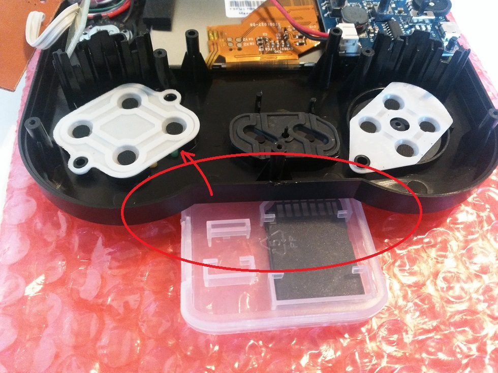
Tip to close the casing : If you let the front casing flat on the table, the buttons will be pushed up. So the silicon may move a little bit resulting in some buttons not working correctly. To help closing you can use a piece of something (the SD box for example) under the casing close to the buttons to prevent them to push up.
If some D-pad buttons don’t work it can be solved by moving a little bit the silicon into the casing
If nothing change open a ticket the PCB is likely faulty and need to be replaced.
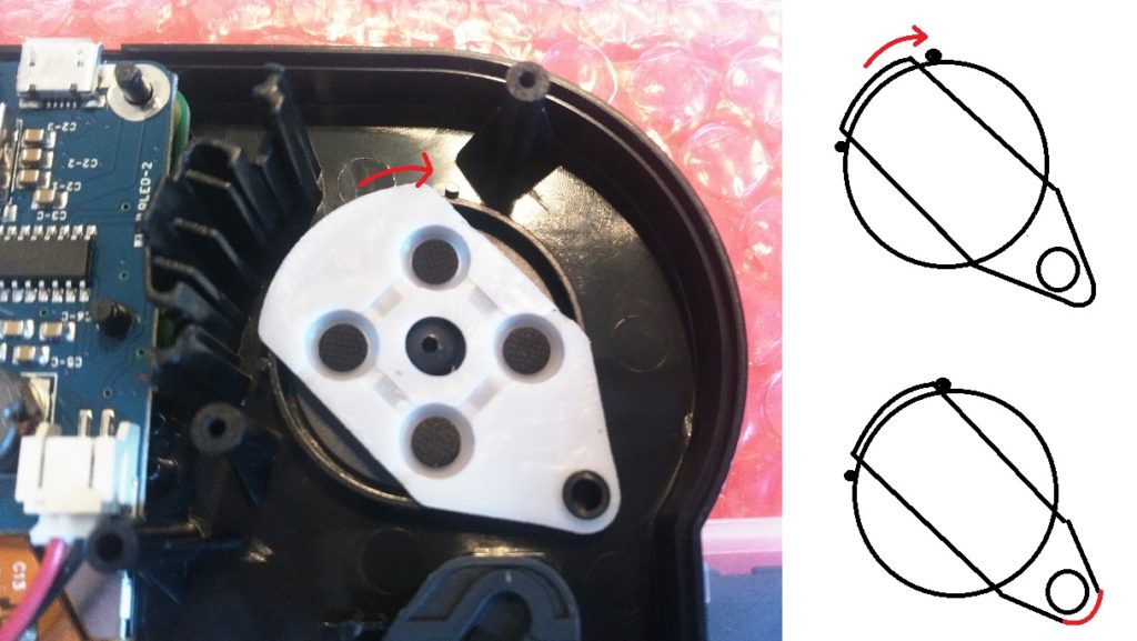
- X button not registering correctly?
This sometimes happens because the PCB is not aligned correctly with the buttons. In order to solve that you can try the following fix :
Cutting the upper right corner of the PCB with scissors as showed on enclosed pictures.
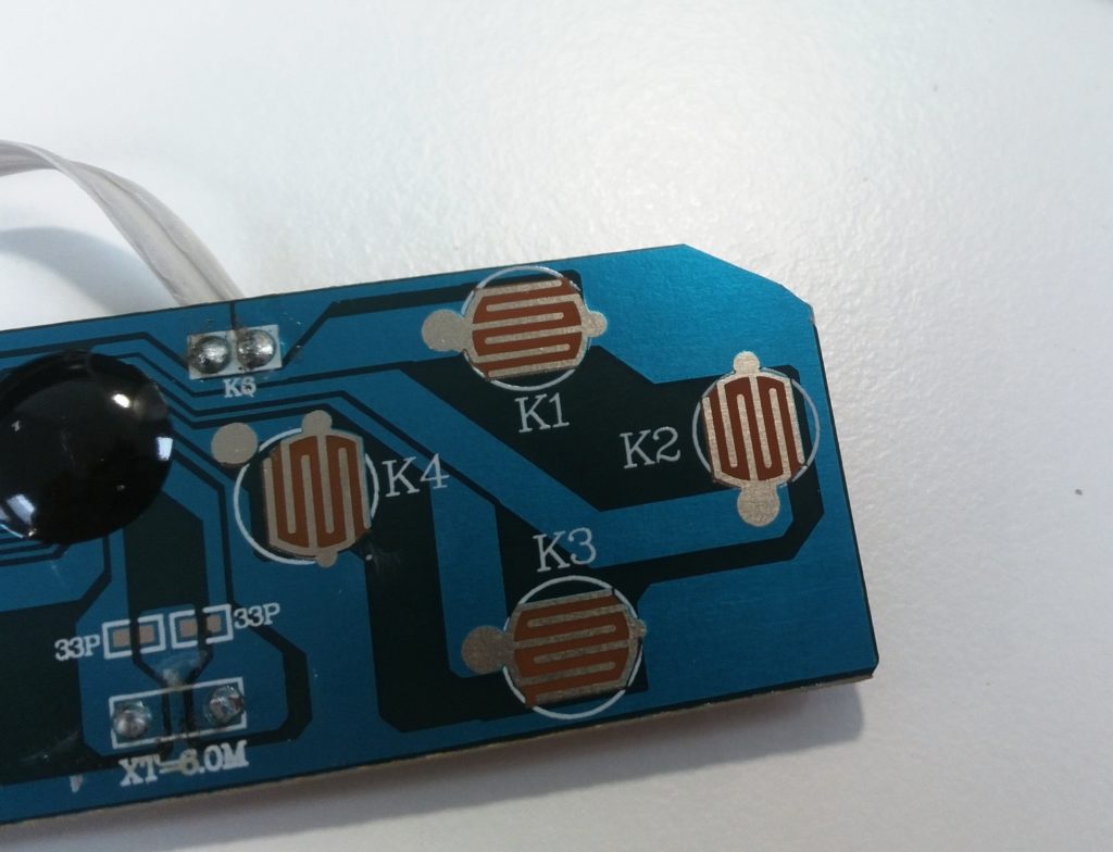
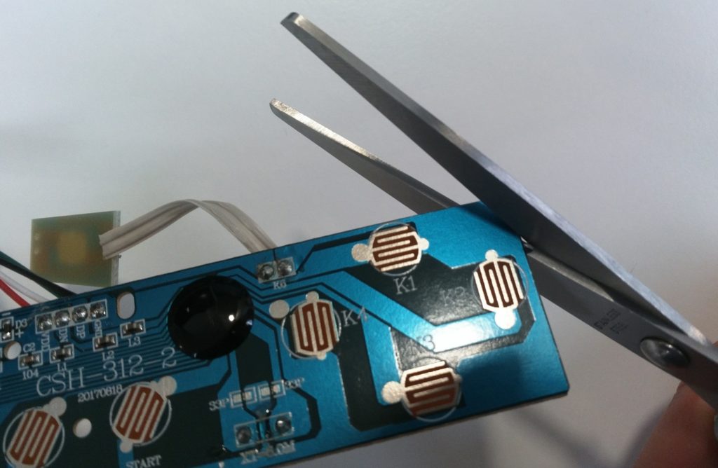
This will help the PCB to move a little bit towards the top, enabling a better alignement.