Please note that modding and/or opening your RetroStone will void your guarantee! Do it at your own risk, doing so might result in product not working anymore or even hurting yourself. I would suggest doing it only if you know what you’r doing. Be carefull of electrostatic, hold the PCB by the edges only and avoid touching components as much as possible. Also make sure to ground yourself.
A – Adding 2 additional buttons
Level : moderate
Tools required :
- scissors
- Drill with 10mm wood bit
- Hand file or sand paper
- Screwdriver (philips 2mm or such)
Material needed :
- Supplied buttons and silicon packet (should be in your retrostone box, check under the paper blister)
Let’s go!
Step 1 : Unscrew the 6 screws
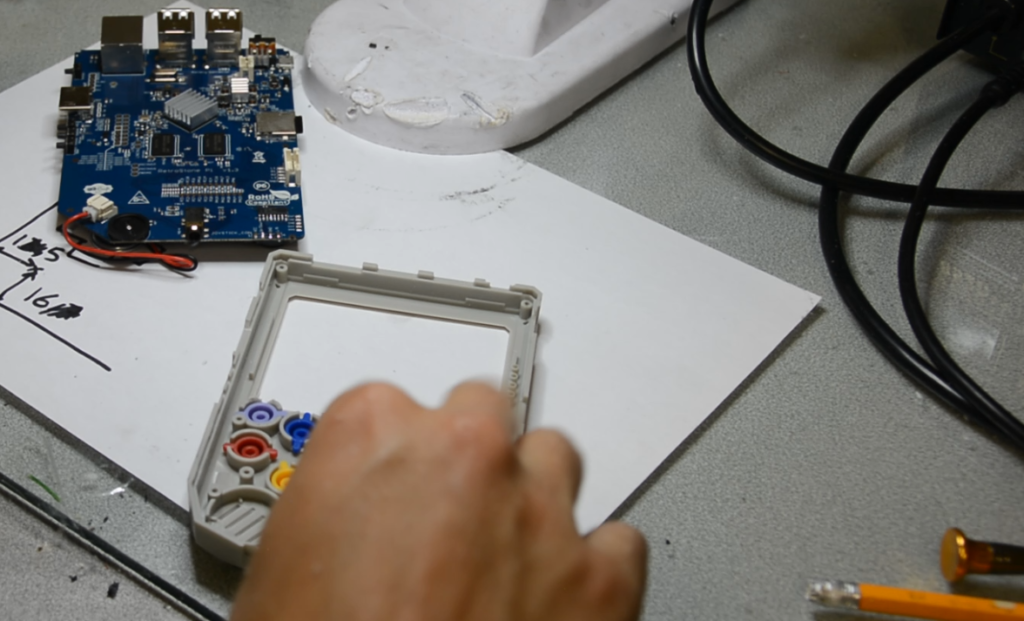
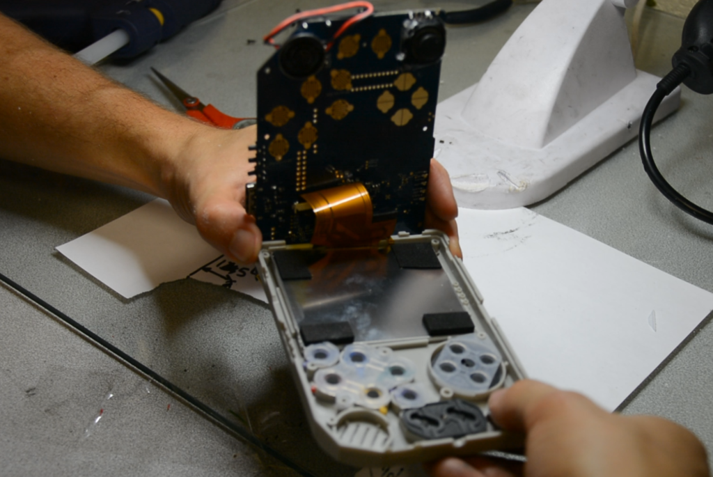
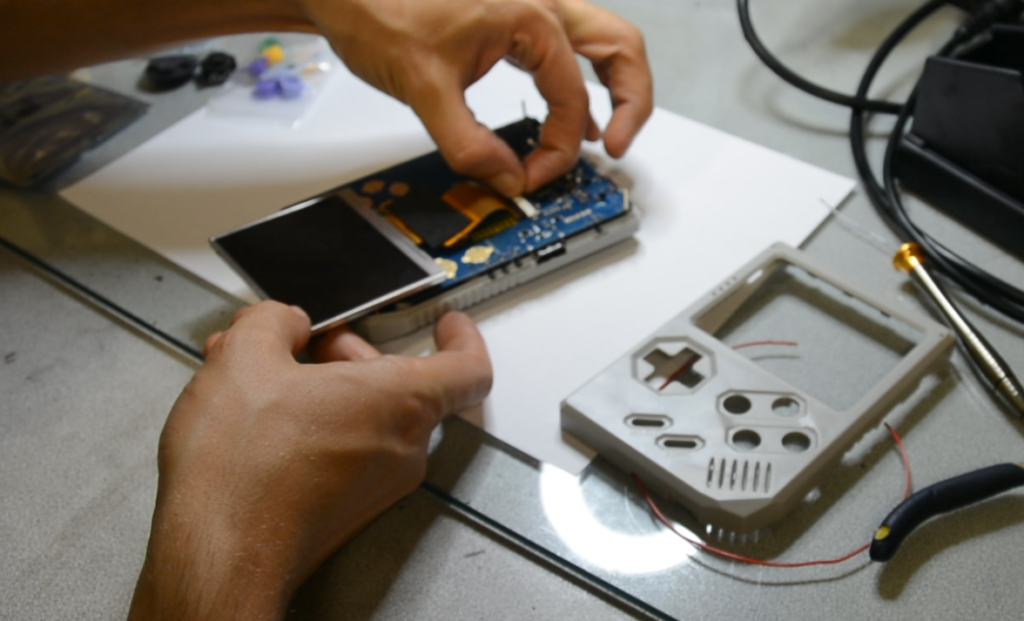
Step 2 : Remove the front casing (be gentle!) You can push the LCD down so it don’t come with the casing.
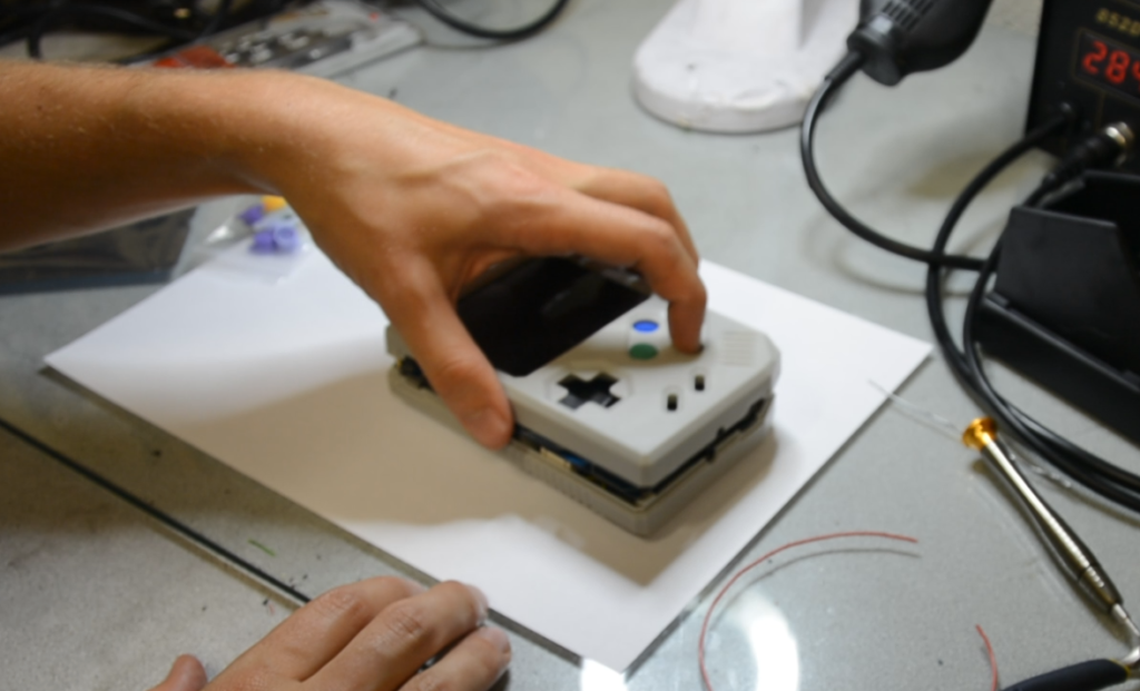
You can let the PCB in the back casing, you won’t need to separate them for additional buttons.
Step 3 : Drill the holes in the button layout
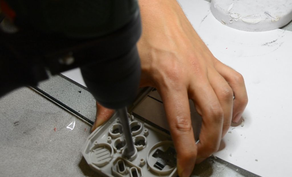
Step 4 : Clean the hole interior with a small rounded hand file, and file to get a clean angle that match RetroStone design. (don’t file too much at once or you might file too much plastic! Do it slowly, going all the way around to make sure it’s even)
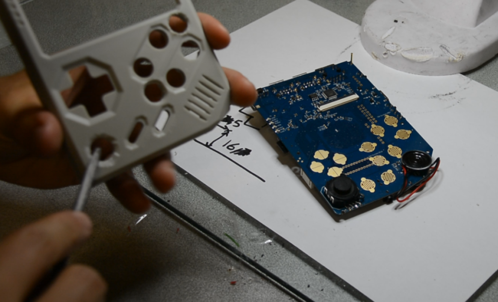
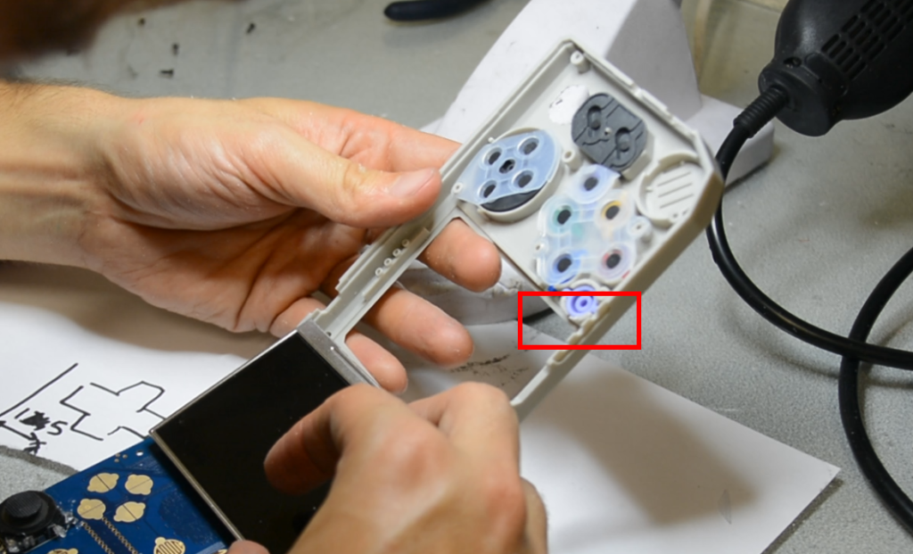
Step 5 : Drilling might have deformed the plastic for the upper button hole (see below red rectangle). This might prevent the LCD from fitting correctly in it’s hole. Check if the LCD can fit correctly in it’s socket (you might want to unconnect the LCD to do so. Or alternatively if you don’t want to unconnect LCD, you can just check if plastic is still flat on the LCD side of the plastic wall). If plastic is not flat use your hand file to flatten the LCD plastic socket. Make sure the button can still move correctly afterwards. If not file again on the button side of the wall.
Step 6 : Test if buttons can move correctly in the new holes without friction.
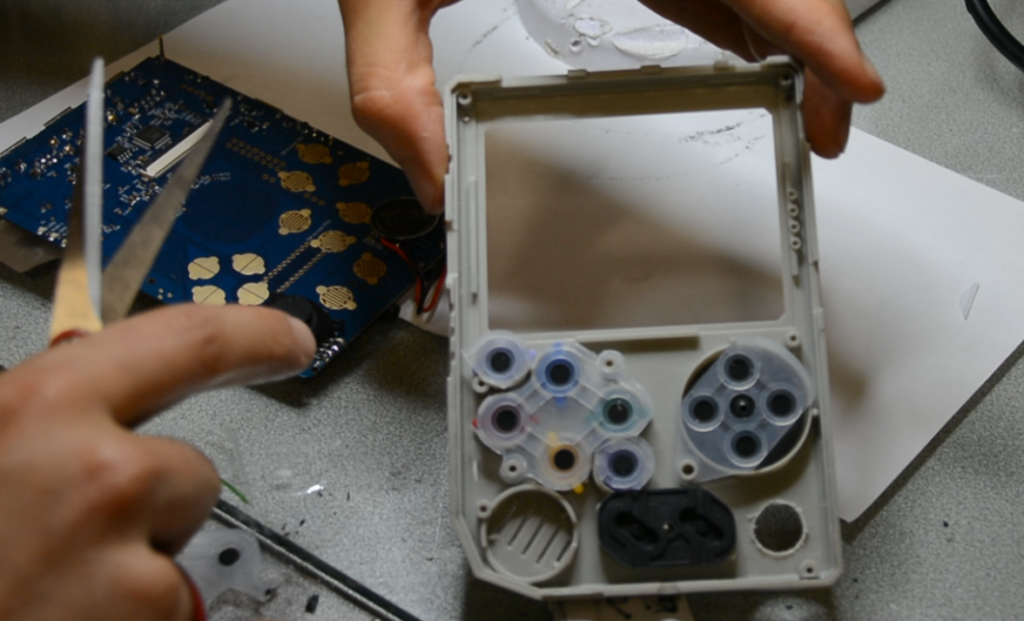
Step 7 : Cut two round silicone with conductive pads in the additional silicone. You can also cut the main silicon border so the new round silicones can fit.
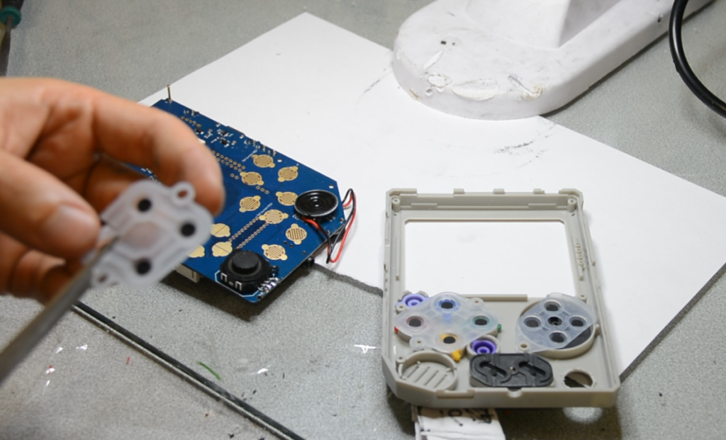
Step 8 : Put the silicone in place and make sure they don’t overlap with other silicones and with the screw hole/pillar.
Step 9 : Put the LCD in it’s socket (in your case the PCB and back casing should still be together, no need to separate them. I removed them because I also added joystick at the same time)
Step 10 : Bring down the PCB and backcasing together. Do it slowly so the silicon don’t move!
Step 11 : Before screwing them together, hold them together and test the buttons to see if they click correctly. If they don’t then maybe you did not filed enought!
Step 12 : Buttons are working OK? Just screw the back casing. Don’t screw too hard! Or the plastic will be torned and screws won’t hold anymore.
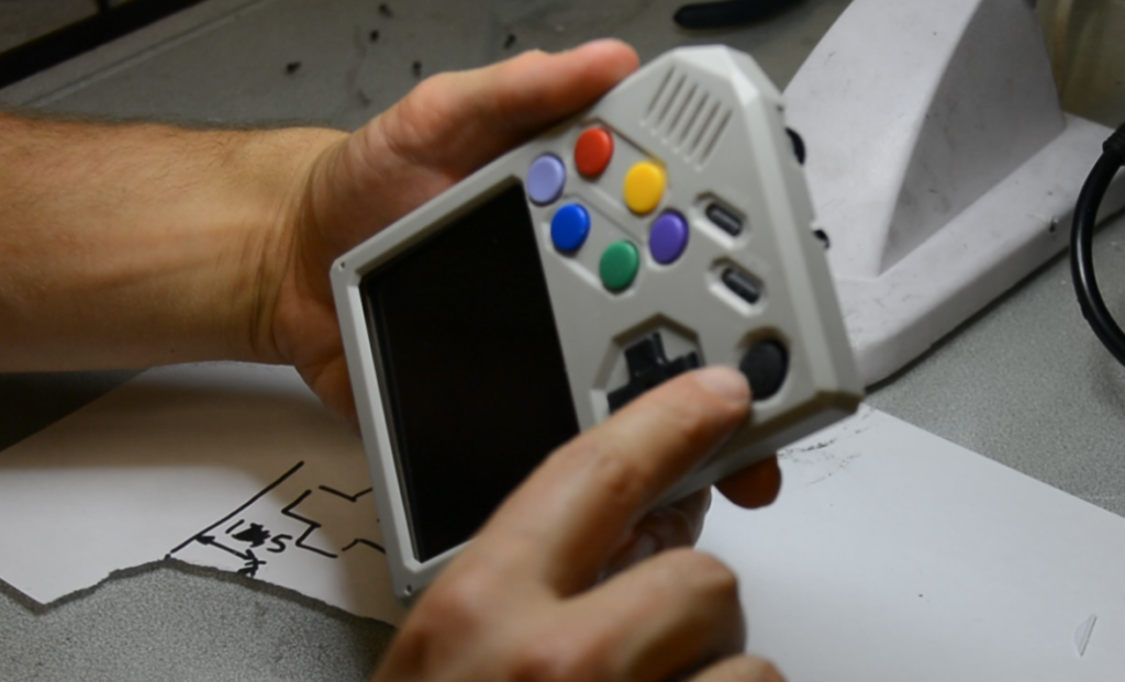
The buttons should work out of the boxe, just go to emulation station, press start, go to “configure input” and map the keys including the 2 new buttons.
B – Adding analog joystick
IMPORTANT : Joystick driver is not yet functional!
Level : Difficult
Tools required :
- Solder iron
- Hot air solder station (optional)
- Drill with 12mm wood bit (or 10mm and filing a bit)
- Hand file or sand paper
- Screwdriver (philips 2mm or such)
Material needed :
- MCP3208 SMD SOIC package (here for example)
- Analog joystick (like this one)
Let’s go!
Step 1 : Unscrew the 6 screws
Step 2 : Remove the front casing (be gentle!) You can push the LCD down so it don’t come with the casing.
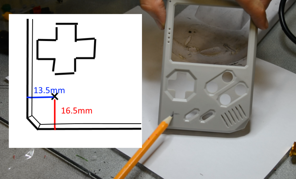
Step 3 : Mark where you’ll be drilling. It should be 13.5mm from the side and 16.7mm from the bottom (extreme side and bottom)
Step 4 : Drill the hole with wood bit. For the joystick model I’m using you need a hole of 12mm for the joystick to move correctly. You can use 12mm wood bit or 10mm bit and file a bit.
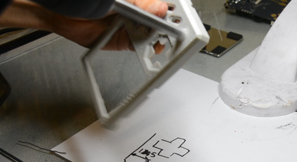
Step 5 : Clean the hole interior with a small rounded hand file, and file to get a clean angle that match RetroStone design. (don’t file too much at once or you might file too much plastic! Do it slowly, going all the way around to make sure it’s even)
Step 6 : Disconnect the LCD.
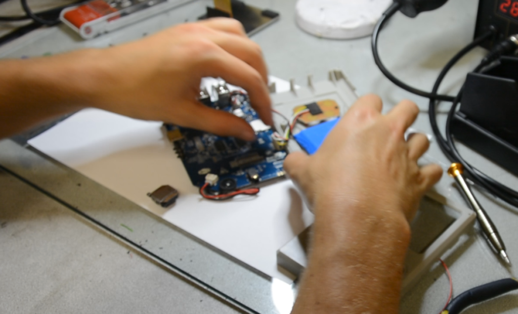
Step 7 : Flit the unit over and remove gently the back casing and disconnect back buttons and battery.
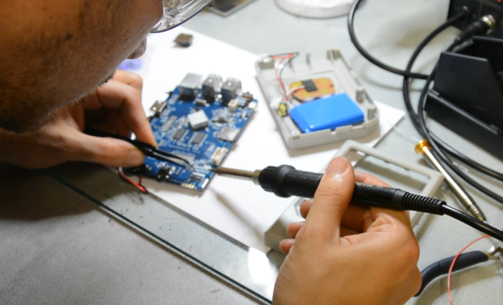
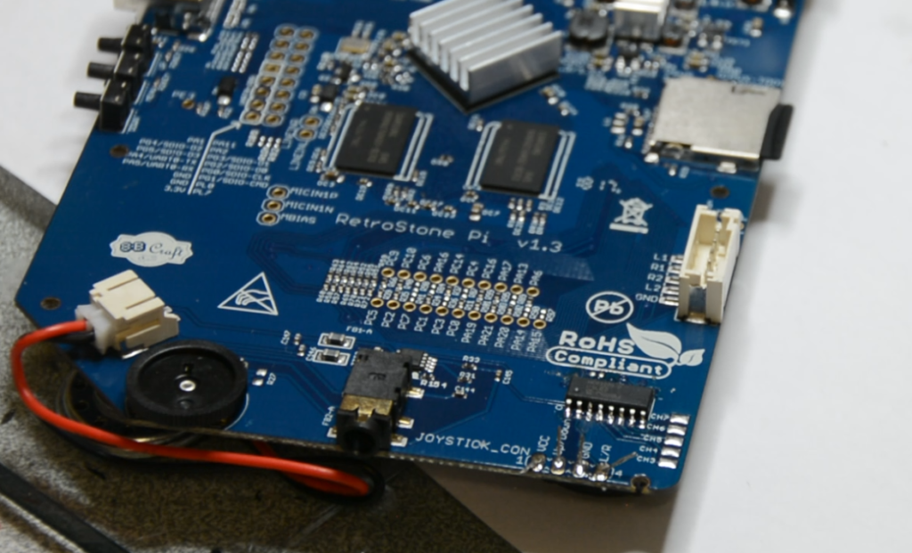
Step 8 : Solder the MCP3208, if you have hot air solder station you can use it, or just use regular (small) solder iron. Check on youtube how to solder chips if you don’t know how. Don’t solder it reversed side ! The writing on the chips should be the same side as the writing on the PCB.
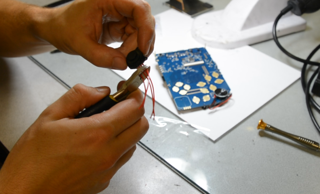
Step 9 : Solder 4 wires on your joystick (you can use tape to fix the joystick while you’r soldering the wires
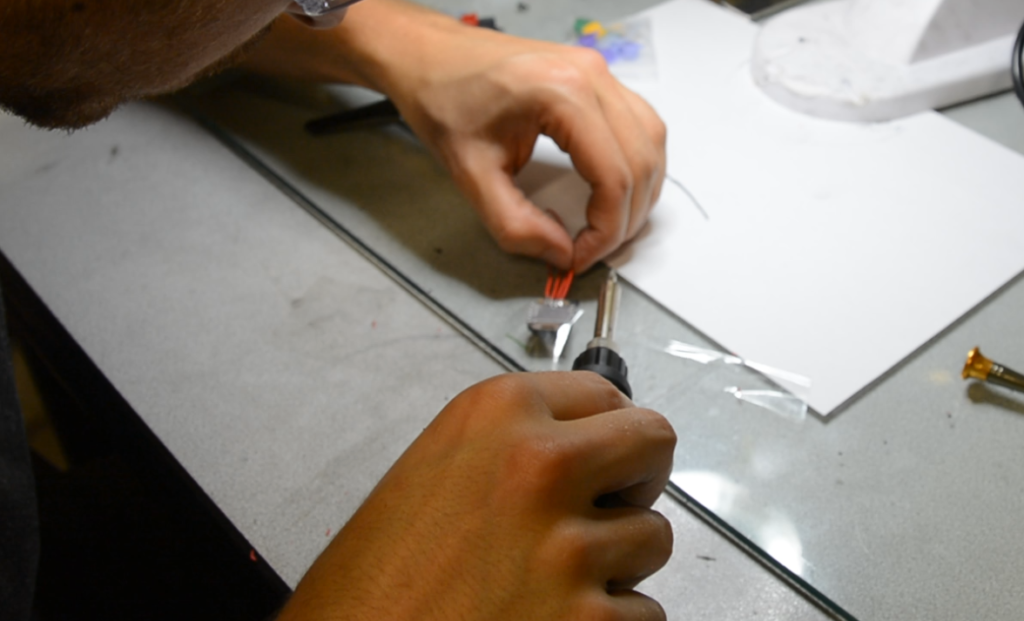
Step 10 : Cut the wires at the correct lenght and strip them to you can solder them on the PCB
Step 11 : Insert the wires in the holes
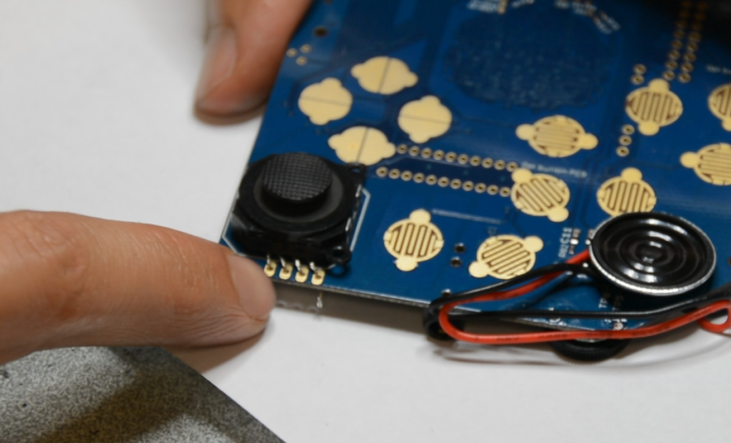
Step 12 : Make sure the joystick is centered very well on the PCB layout (the white printing) before soldering!
Step 13 : Add a bit of hot glue to hold down the well centered joystick.
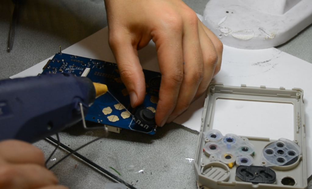
Step 14 : Solder the 4 wires. (please note that if you don’t use the same model of joystick you need to check the pinout of your joystick in order to solder correctly the joystick!)
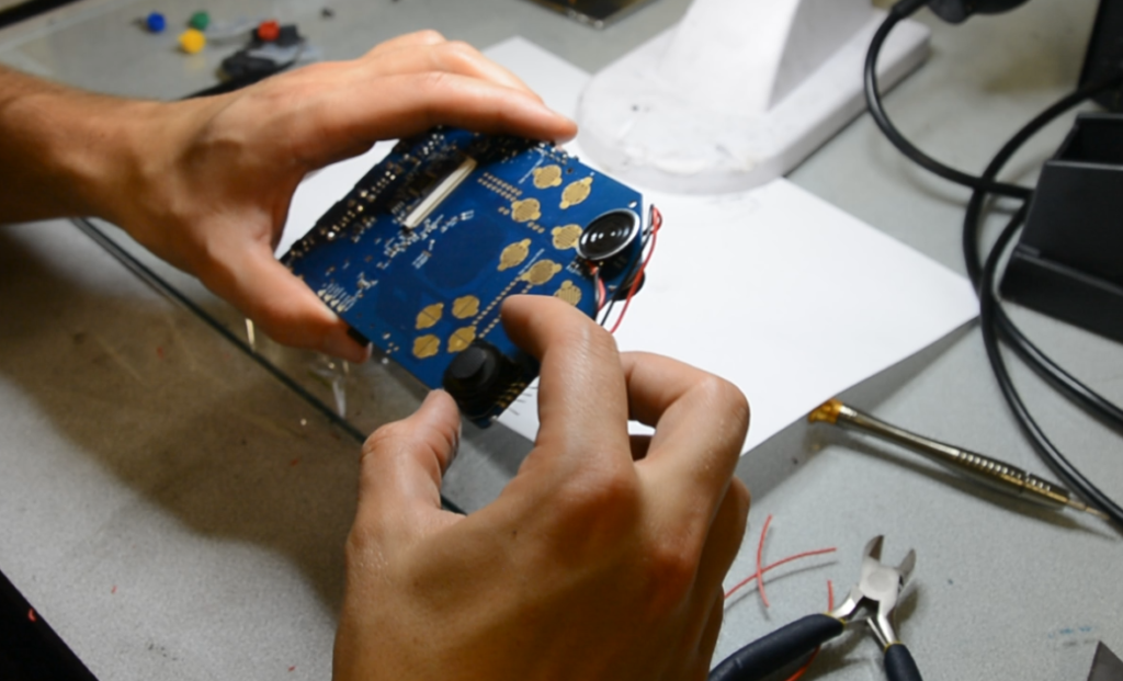
Step 15 : Apply the front casing to make sure the Joystick can move correctly. If it can’t move correctly, fix what is the problem (maybe too much hotglue? Maybe not filed enought? …)
Step 16 : Reassemble : first put all buttons and silicons. Then put the LCD back in it’s socket.
Step 17 : Bring down the PCB and backcasing together. Do it slowly so the silicon don’t move!
Step 18 : Before screwing them together, hold them together and test all the buttons and the joystick to see if they click/move correctly. If they don’t then maybe you did not filed enought!
Step 19 : Everything OK? Just screw the back casing. Don’t screw too hard! Or the plastic will be torned and screws won’t hold anymore.
The buttons and joystick should work out of the boxe, just go to emulation station, press start, go to “configure input” and map the keys including the 2 new buttons.